Pipe Schedule Method for Firefighting Sprinkler System

Pipe Schedule Method for Firefighting Sprinkler System
The water demand for firefighting sprinkler systems shall be determined by either the pipe schedule method or the hydraulic calculation method, in this article we will discuss the pipe schedule method.
What is pipe schedule system?!
According to NFPA 13, Pipe Schedule System is defined as sprinkler system in which the pipe sizing is selected from a schedule that is determined by the occupancy classification and in which a given number of sprinklers are allowed to be supplied from specific sizes of pipe.Where can we use pipe schedule method?!
- New systems of 465 m2 or less.
- Additions or modifications to existing pipe schedule systems.
Classification of occupancies according to hazard
NFPA 13 classifies the occupancies according to the quantity and combustibility of contents, the expected rates of heat release, the total potential for energy release, the heights of stockpiles, and the presence of flammable and combustible liquids as the followings:
Light hazard occupancy
Spaces with low quantity and combustibility of contents.
Examples: Churches, clubs, hospitals, restaurant seating area, offices buildings, and etc.
Examples: Churches, clubs, hospitals, restaurant seating area, offices buildings, and etc.
Ordinary hazard group (1) occupancy
Spaces with moderate quantity and low combustibility of contents, or stockpiles of contents with low combustibility that do not exceed 2.4 m.Examples: Bakeries, beverage manufacturing, automobile parking, restaurant services area, and etc
Ordinary hazard group (2) occupancy
Spaces with moderate to high quantity and combustibility of contents or Stockpiles of contents with moderate to high combustibility that do not exceed 3.7 m.Examples: Dry cleaners, feed mills, barns or stables, textile manufacturing, and etc.
Extra hazard group (1) occupancy
Spaces with very high quantity and combustibility of contents or Spaces where dust, lint, or other materials are present, introducing the probability of rapidly developing fires.
Examples: Aircraft hangers, die casting, metal extruding, saw mills, and etc.
Examples: Aircraft hangers, die casting, metal extruding, saw mills, and etc.
Extra hazard group (2) occupancy
Spaces with very high quantity and combustibility of contents or Spaces with substantial amounts of combustible or flammable liquids or Spaces where shielding of combustibles is extensive
Examples: Asphalt saturating, flow coating, flammable liquids spraying, and etc.
Examples: Asphalt saturating, flow coating, flammable liquids spraying, and etc.
High-piled storage occupancy
Solid-piled, palatalized, rack storage, bin box, and shelf storage in excess of 3.7 m in height.Pipe schedule according to hazard degree:
The table below summarizes the pipe schedule for each hazard degree:
Pipe schedule according to hazard degree
Note that: the column for the extra hazard occupancies is just used as a guide for only extensions for existing systems, while new extra hazard occupancies shall be hydraulically calculated.
Pipe schedule for sprinklers above & below ceiling:
The table below summarizes the pipe schedule for systems where there are sprinklers above & below ceiling: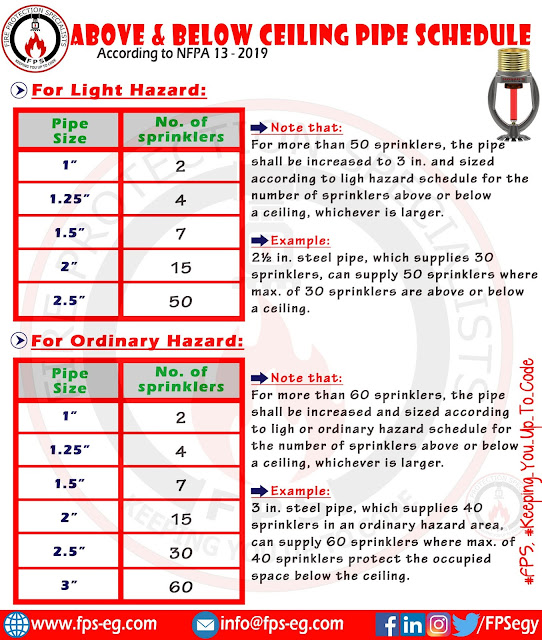
Pipe schedule for sprinklers above & below ceiling
Minimum water supply requirements for pipe schedule systems:
The table below summarizes the minimum water flow rate, residual pressure, and duration of pipe schedule systems: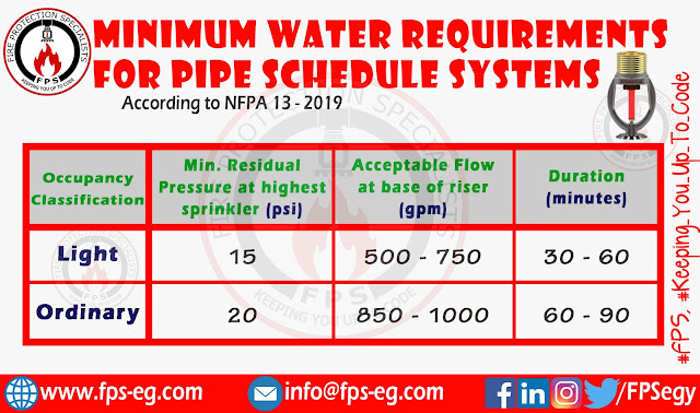
Minimum water supply requirements for pipe schedule systems
Note that:Pipe schedule method can be used to determine the system demand for new systems exceeding 465 m2 where the flow required as above table is available at a minimum residual pressure of 50 psi.
The lower duration value is accepted only where water flow alarm devices & supervisory devices are electrically supervised & monitored.
The lower flow figure shall be permitted only where building is of noncombustible construction or no open areas exceed 280 m2 for light hazard or 370 m2 for ordinary hazard.
The friction losses of back flow prevention devices shall be accounted for when determining acceptable residual pressure at the top level of sprinklers, this value shall be added to the elevation loss and the residual pressure to determine the total pressure needed at the water supply.
Nice
উত্তরমুছুন